Failure simulation and analysis
This section addresses the following aspects:
- Describe the concept of a user-defined Shared Risk Group (SRG), used by ENP to represent network vulnerabilities.
- Describe how the network reaction to failures is simulated.
- Show how it is possible to observe the network reaction under manually generated failure situations.
- Show how to produce tests that automatically analyze the network fault tolerance, to user-defined potential vulnerabilities.
Shared Risk Group (SRG)
Shared Risk Groups (SRGs) are a central element in ENP for failure analysis.
An SRG represents a network vulnerability, that is, a potential risk to the network operation. For instance, a hardware malfunction causing the failure of an IP port, or a duct cut causing the simultaneous cut of all the optical fibers in it (and thus of all the traversing optical circuits).
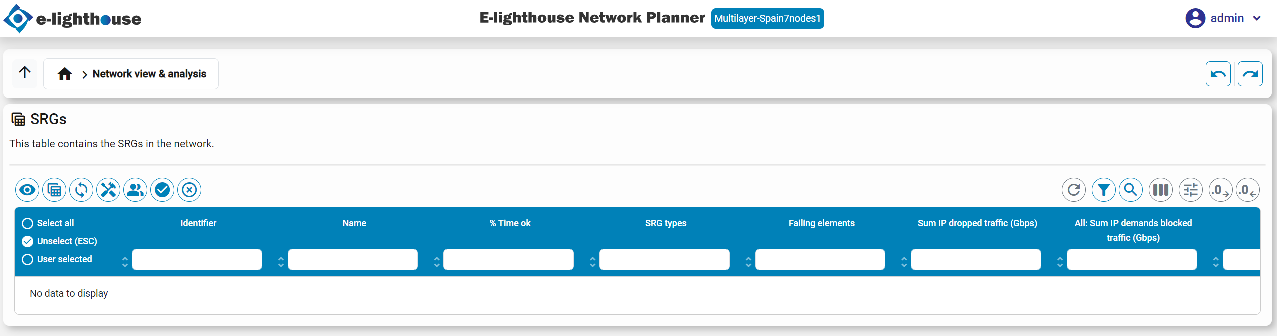
Users can define, manipulate, and access to different operations with SRGs via the SRG table.
An SRG is characterized by:
- Affected resources. This is the set of resources that simultaneously fail when the risk associated with the SRG occurs. Affected resources can be any user-defined combination of:
- Network nodes. When a node fails, all its input and output links or circuits at any layer also fail.
- IP logical ports. The in/out IP links in that port also fail.
- IP injection links. These links can no longer carry traffic, and eBGP sessions in it are down.
- IP adjacencies. Identified by two IP nodes. The failure of an adjacency implies the failure of all the IP links in that adjacency.
- WDM links. All the optical channel (OCh) paths traversing it are down. If the WDM link is protected in a 1+1 configuration, both the main and backup link has to be down for this to happen.
- Mean Time To Repair (MTTR). Defined as the average time (in number of days), from the moment that this risk has happened (and thus all affected resources are set to down), to the moment in which this failure is repaired, and all associated resources are set to up.
- Mean Time To Fail (MTTF). Defined as the average time (in number of days), from the moment that this risk was repaired, to the moment in which it fails again.
- SRG types. Each SRG can belong to zero, one or more SRG types. This is just a classification the user can define, in order to be able to assign fault-tolerance requisites individually for different IP or ODU traffic demands.
When MTTF and MTTR information is introduced, ENP is able to exploit it in several aspects.
Note
Note that the SRG concept in ENP permits representing single failures or multiple simultaneous failures in a single SRG. That is, the user has full flexibility to define SRGs representing regular failure situations like a node failure, or catastrophic failure situations like a simultaneous failure in multiple links and nodes caused e.g. by a natural disaster.
Fine-grained fault tolerance targets
ENP permits the user to define different fault-tolerance targets to different IP demands / IP multicast flows / ODU requests, by creating different SRG types, and assigning them to different demands
Example. A network has two types of IP demands: (i) regular demands that should be fault tolerant to single IP node failures, (ii) critical demands that should be fault tolerant to single IP node failures and to single WDM link failures. To represent this failure tolerance profile in ENP we can:
- Create all the required single IP node SRGs, and assign them to the regular SRG type
- Create all the required single WDM link SRGs, and assign them to the critical SRG type
- Those IP demands that are regular, should be assigned to the SRG group regular.
- The critical IP demands should be assigned to two SRG groups regular and critical
This fine-grained fault-tolerance requisite are considered in the analysis tools described in this section. Additionally, the ENP network design functionalities will optimize the network design according to the defined fine-grained fault-tolerance requisites
Adding SRGs
ENP provides two main forms for adding SRGs to a network design, via the appropriate right-click options in the SRG table:
- Manually. The SRGs can be added one by one, and later edited with this right-click option.
- Automatically. ENP provides different methods to automate the addition of SRGs. They are accessible via the multiple submenus of the Add SRGs from the model menu in the SRG table. For instance, adding one SRG for each single-node failure, single WDM link failure, etc. In any case, the MTTF/MTTR and the rest of the SRG information can be manually edited after the creation, using the manual SRG edition methods mentioned above.
Multilayer simulation of the network failures
ENP simulates the network failures in a multilayer network, applying the following procedure:
- Optical transport recovery. OTN recovery mechanisms are applied first:
- WDM paths that are down (manually set as down, or traverse a failed node), are identified.
- WDM links that consist of one WDM path are down if such a path is down. WDM links protected by 1+1 WDM paths are down, if both the main and backup WDM path is down.
- Optical Channels (OCh) paths that traverse a failed node or a failed WDM link are considered down.
- Optical Channels (OCh) that are realized by a single OCh path, are considered as failed if its path is failed. OChs that are realized via two 1+1 OCh paths are considered failed if both paths are down.
- Optical Transport Unit (OTU) paths that traverse a failed OCh are considered down. If the OTU restoration is active for the failed OTU path, then the OTU restoration algorithm is applied for the OTU path, that searches for a valid OTU non-failed path. If such a route is found, the OTU is considered as non-failed.
- Optical Transport Units (OTUs) that are realized by a single OTU path, are considered as failed if its path is failed. OTUs that are realized via two 1+1 OTU paths are considered failed if both paths are down
- Optical Data Unit (ODU) paths that traverse a failed OTU are considered down. If the ODU restoration is active for the failed ODU path (see here), then the ODU restoration algorithm is applied for the ODU path, that searches for a valid ODU non-failed path. If such a route is found, the ODU is considered as non-failed.
- Optical Transport Units (ODUs) that are realized by a single ODU path, are considered as failed if its path is failed. ODUs that are realized via two 1+1 ODU paths are considered failed if both paths are down
- IGP/BGP recovery. IP/BGP recovery is assumed to occur after OTN recovery is completed.
- IP ports set as down or hosted in down nodes, are considered as failed.
- IP connections transported via a failed ODU are assumed to be down.
- The full IGP/BGP and MPLS scheme is simulated considering only the surviving IP resources.
Note
Important. The OTU and ODU recovery algorithms can be implemented in a customized form to reflect the particular behavior of the equipment in place, in the form in which the restoration paths are computed. The default behavior is:
- OTU restoration. A new OTU path is searched in the same form as if the failed OTU did not exist, and a new OTU is requested between the same end nodes and for the same rate. This means using optical OEO regeneration when needed and permitted by the equipment.
- ODU restoration. A new ODU path with enough idle capacity is searched, applying shortest path criteria (minimizing end-to-end latency).
Manual failure what-if analysis
ENP permits the user to observe the network reaction under manually defined failures. For that, the user can produce failures and repairs in different resources as follows:
-
Setting the up/down failure state of any of the node inventory tables.
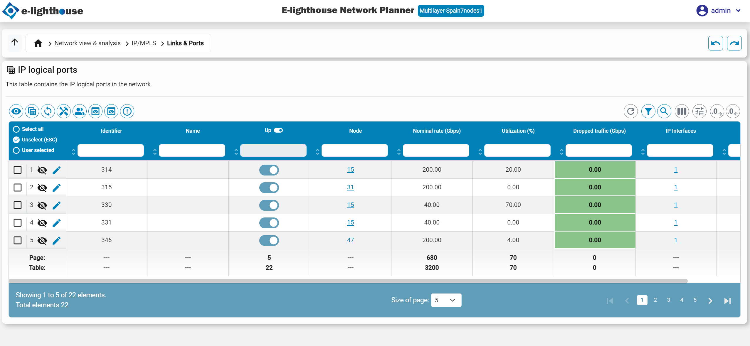
-
Setting the up/down failure state of IP logical ports in the IP logical ports table.
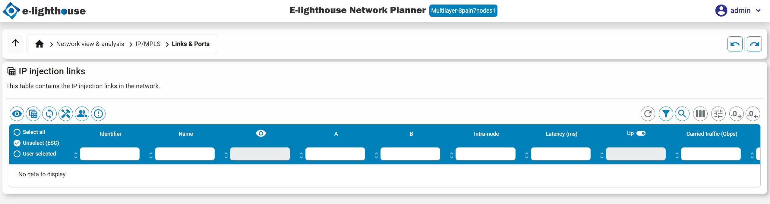
- Setting the up/down failure state of IP injection links in the IP injection links table.
- It is possible to set the up/down failure state of all the associated resources of an SRG, via the appropriate right-click option in the SRG table.
After manually configuring a network with an arbitrary arrangement of up/down states in their elements, the user can observe and analyze the full network information performances in such state, e.g.:
- Browsing the multilayer information in the View/edit network state tables, that are updated to reflect the new situation (that is automatically simulated).
- Navigating up and down the multilayer network in the Drill up/down panels.
- ...
Automatic network vulnerability analysis
ENP permits creating an automatic bulk analysis of the network fault tolerance under all the user-defined defined network vulnerabilities.
The user can access such analysis by clicking in the icon:

When this happens:
- ENP sequentially simulates the network reaction in the non-failure state, and in all the single-SRG failure states, for all the user-defined SRGs. ENP collects statistical information e.g. accounting for the surviving and non-surviving traffic, the end-to-end latencies, congestions, etc. in all situations.
- Statistical results for the non-failure state, and for the worst-case situation are derived and shown to the user in an organized form in the tables:
- IP demands table.
- IP logical ports table.
- IP VPN table.
- IP multicast flows table.
- SRGs table.