Create Your First Network Design
In this walkthrough, you'll build a minimal working network design using the E-Lighthouse Network Planner (ENP) Web Client. We'll create a topology with three router nodes and connect them using IP links.
This tutorial assumes you've already created and loaded a new design. If not, please start with:
👉 How to Create a New Network Design
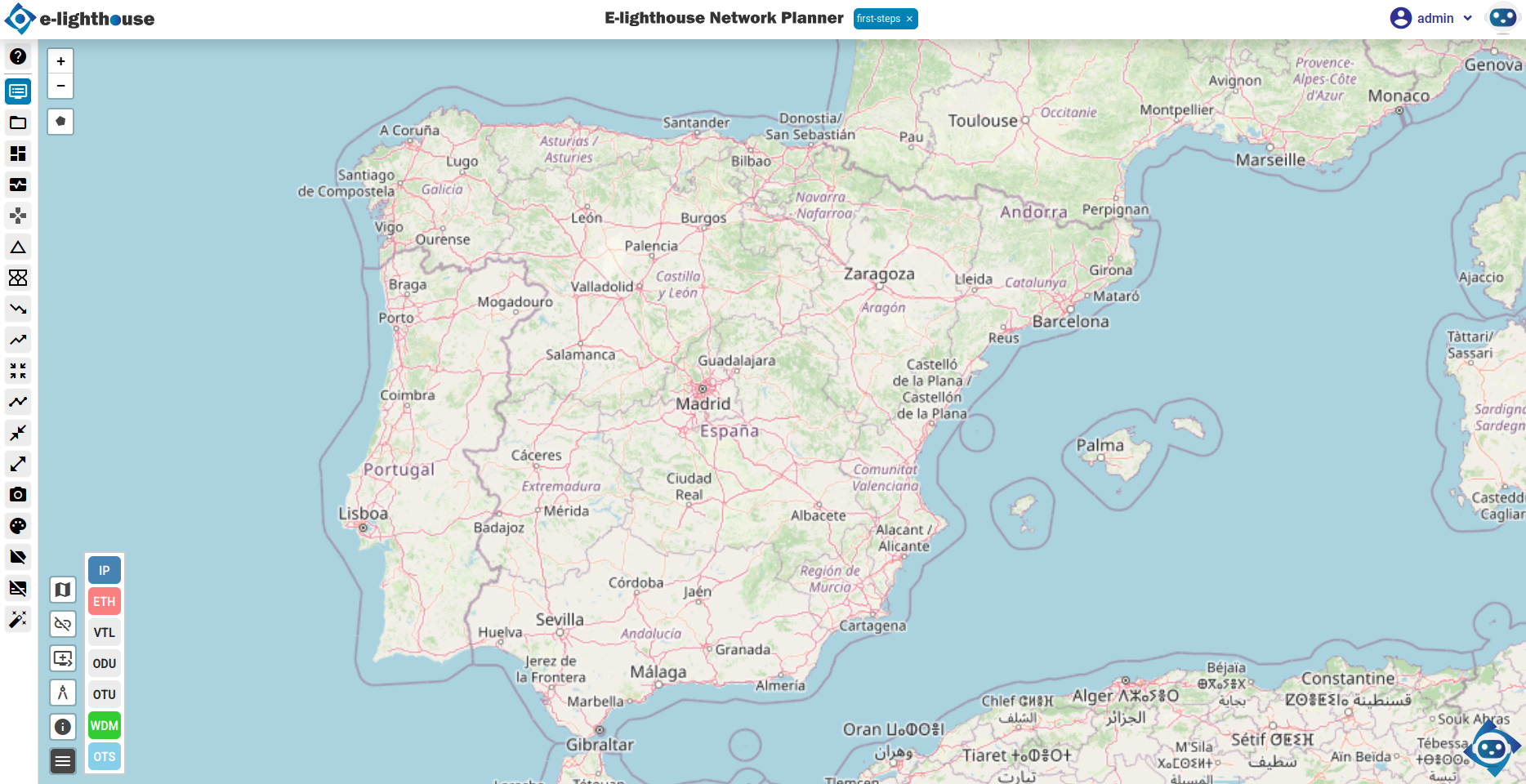
🧱 Step 1: Open the Topology View
Once your design is loaded, you should see the Topology View window — your workspace for constructing and visualizing network topologies.
🧩 Step 2: Add Three Router Nodes
Use the right-click context menu to add nodes to your topology.
- Right-click on the map where you want to place the first router.
- Click the "Node" button (usually a "+" icon).
- Select "Add node of type IP Router".
- In the properties panel, set the Node name to
R1. - Repeat this process to create nodes
R2andR3.
💡 Tip: If your nodes are not visible on the map, check the "Hide non-connected nodes" toggle at the bottom-left corner of the map. Disabling this will reveal all nodes, including those not yet linked.

🔗 Step 3: Connect Nodes with IP Links
Now, let’s connect the routers using IP links.
- Right-click on the origin node (e.g.,
R1) and choose "Create a new link". - Click the destination node (e.g.,
R2). A link configuration panel will appear. - Choose "Add IP link over virtual transport connection".
- Set the following link properties:
- Link name:
R1-R2 - Nominal rate:
100 Mbps - Repeat the process to add:
- A link from
R2toR3 - A link from
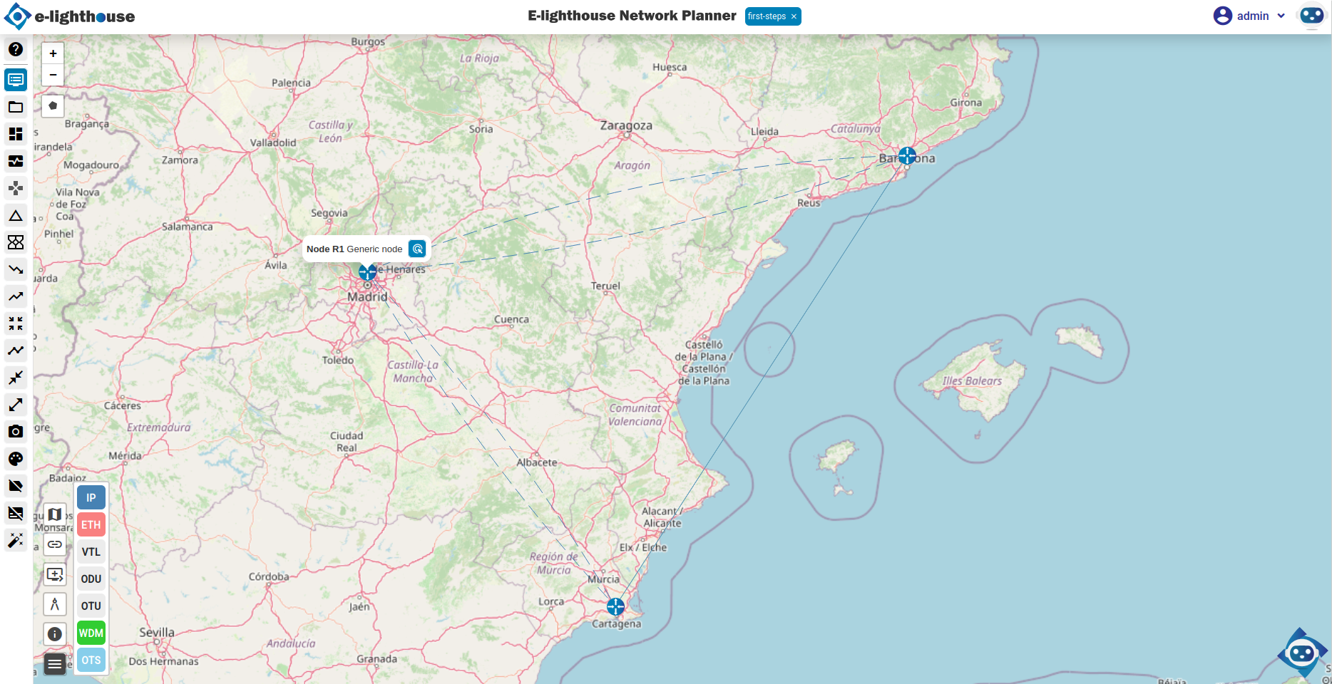
R3toR1
At this point, you should have a triangle topology connecting all three routers.
🧠 Step 4: Review Node and Link Properties
You can use the Control Window to inspect and fine-tune node and link attributes.
- Open the Control Window from the top menu.
- Navigate to the Network View & Analysis section.
- Check the Nodes table for information on node metadata.
- In the IP/MPLS folder, go to the Links & Ports subfolder.
- Select the IP Links table to review and edit your created links.
All changes are automatically saved within the current session.
💾 Step 5: Save the Design
Click Save Design in the top menu to persist your changes.
Your design is now ready for simulation or further enhancements.
✅ Summary
You’ve successfully created your first functional network design:
- 🧱 3 IP router nodes
- 🔗 Connected with IP links forming a triangle topology
- 🗺️ Fully visualized in the Topology View
This forms the foundation for exploring simulations, analytics, and network behavior modeling.